Author Topic: Coolant flow chart  (Read 3002 times)

0 Members and 1 Guest are viewing this topic.

Offline Gmg31

  • Hero Member
  • *****
  • Joined: Jul 2015
  • Location: teesside
  • Posts: 580
Coolant flow chart
« on: Friday,January 22, 2016, 11:12:59 AM »
Can anyone point me to a simple flow chart for all the coolant and heater hoses on the Renault engine please. I didn't get to take this apart so at the moment I'm just looking at everyone's photos and its lot quite clear enough.

Offline jbcollier

  • Super Member
  • *******
  • Joined: Nov 2013
  • Location: Edmonton, Alberta, Canada
  • Posts: 5,811
Re: Coolant flow chart
« Reply #1 on: Friday,January 22, 2016, 11:40:56 AM »
Standing at the back and looking to the front:

- coolant flows out the water pump's outlet on the RH side (thermostat is in this hose).

- coolant flows into the swirl pot and back into the engine in the water pump's I let on the LH side.

All other connections can be reduced by which side of the pump they are located on.

In the front compartment the coolant flows in the bottom of the radiator and out the top.

Helpful?

Offline Gmg31

  • Hero Member
  • *****
  • Joined: Jul 2015
  • Location: teesside
  • Posts: 580
Re: Coolant flow chart
« Reply #2 on: Saturday,January 23, 2016, 08:48:55 AM »
Thanks, I seem to have more connections than I can make sense of.

Offline jbcollier

  • Super Member
  • *******
  • Joined: Nov 2013
  • Location: Edmonton, Alberta, Canada
  • Posts: 5,811
Re: Coolant flow chart
« Reply #3 on: Saturday,January 23, 2016, 09:38:29 AM »
The Renault water pump has a myriad of connections.  We have covered the two large ones which are the inlet and outlet to/from the rad, and the mid-size ones for the heater.  The remaining two are for hot water to the stock carb and a system bleed.

https://jbcollier.smugmug.com/Lotus-Europa/i-99VpNDT/A

It is very important that you a way of bleeding air out of the small outlet at the water pump's high point.

https://jbcollier.smugmug.com/Lotus-Europa/i-3Df756g/A
« Last Edit: Saturday,January 23, 2016, 09:41:38 AM by jbcollier »

Offline jjbunn

  • Full Member
  • ***
  • Joined: Nov 2013
  • Location: Pasadena, California
  • Posts: 166
Re: Coolant flow chart
« Reply #4 on: Saturday,January 23, 2016, 05:47:09 PM »
Bonus for 10: does the coolant water flow into the cabin heater from the left inlet, or the right?

Offline jbcollier

  • Super Member
  • *******
  • Joined: Nov 2013
  • Location: Edmonton, Alberta, Canada
  • Posts: 5,811
Re: Coolant flow chart
« Reply #5 on: Saturday,January 23, 2016, 06:57:23 PM »
Out to the heater next to the thermostat, return from the heater next to the swirl pot.

Offline rascott

  • Full Member
  • ***
  • Joined: Dec 2014
  • Location: california
  • Posts: 249
Re: Coolant flow chart
« Reply #6 on: Saturday,January 23, 2016, 08:12:31 PM »
interesting topic- made me look.
my water pump looks a little different(of course), and has only one port for the carb. heat(?), but has a bleed at the top of the pump body.

there is another port at the back of the head that must be related.

does the flow to heater go to heat valve - to heater- back to pump?
mine didn't when i got it(heat valve was on return), and the rear head port was hosed to the return side of pump("bypassed"?), and, so far, i have followed that path.
i suppose the bypass could be blocked off without harming anything........
did this make sense?
richard

Offline jbcollier

  • Super Member
  • *******
  • Joined: Nov 2013
  • Location: Edmonton, Alberta, Canada
  • Posts: 5,811
Re: Coolant flow chart
« Reply #7 on: Saturday,January 23, 2016, 09:39:19 PM »
On Renault engines the heater valve is on the return side.  If you are not using heat to the carb then plug the outlet at the back of the head and the return at the pump.  Hooking it up and allowing an unrestricted bypass will reduce flow to the radiator.  Keep the bleeder at the high point of the pump.

Offline Grumblebuns

  • Super Member
  • *******
  • Joined: Aug 2012
  • Location: San Diego area
  • Posts: 1,483
Re: Coolant flow chart
« Reply #8 on: Sunday,January 24, 2016, 08:45:12 AM »
Like Richard's S2, I also ran a heater hose from the back of the head to the water pump inlet nipple. To get a cleaner look in the engine compartment, I want to get rid of the hose but don't know what to use to plug up the two nipples without looking like a DPO. Ordinary rubber vacuum caps won't hold up to the heat.

Joji Tokumoto
Fallbrook, Ca   

Offline jbcollier

  • Super Member
  • *******
  • Joined: Nov 2013
  • Location: Edmonton, Alberta, Canada
  • Posts: 5,811
Re: Coolant flow chart
« Reply #9 on: Sunday,January 24, 2016, 08:51:46 AM »
It's a screw in fitting in the head.  Remove it and fit a brass plug.  Carefully tap the inside of the pump fitting and fit a brass plug there as well; or, fit a bleeder on the end of a short hose.


Offline Grumblebuns

  • Super Member
  • *******
  • Joined: Aug 2012
  • Location: San Diego area
  • Posts: 1,483
Re: Coolant flow chart
« Reply #10 on: Sunday,January 24, 2016, 11:01:50 AM »
Excellent idea for using the inlet nipple for the Renault water pump as a high point bleeder.

Offline rascott

  • Full Member
  • ***
  • Joined: Dec 2014
  • Location: california
  • Posts: 249
Re: Coolant flow chart
« Reply #11 on: Sunday,January 24, 2016, 01:05:05 PM »
i suspect gmg31is getting some good info here- i know i am....
naturally, my waterpump seems different, as it has a bleeder valve at the "top" of the pump, instead of a hose port.
now i wonder what the stock carb heater system looks like, 'cause i'd be wondering where another hose was, to put on the waterpump!
love the idea of plugging the head and pump- thanks jbcollier.
a po had hose/tubed a bypass to the head, and put a bleed valve in it. i can see being able to eliminate it now.

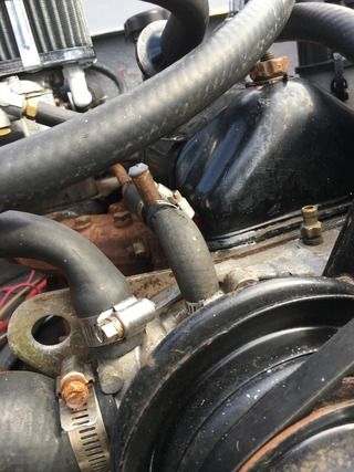
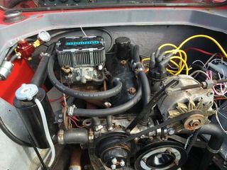
things are still rough, but i've been trying to neaten things up.... got hoses all over the place.

richard

Offline BDA

  • Super Member
  • *******
  • Joined: Jul 2012
  • Location: North Carolina
  • Posts: 9,512
Re: Coolant flow chart
« Reply #12 on: Sunday,January 24, 2016, 02:11:24 PM »
Big improvement! Some stainless steel braided lines would REALLY dress it up!

Offline Gmg31

  • Hero Member
  • *****
  • Joined: Jul 2015
  • Location: teesside
  • Posts: 580
Re: Coolant flow chart
« Reply #13 on: Thursday,January 28, 2016, 01:10:19 PM »
Thank you all for your excellent advice. I'm hoping to start this phase next week. I'll share some photos on my restoration thread. Cheers

Offline BDA

  • Super Member
  • *******
  • Joined: Jul 2012
  • Location: North Carolina
  • Posts: 9,512
Re: Coolant flow chart
« Reply #14 on: Thursday,January 28, 2016, 05:02:23 PM »
Can't wait!